
Optimized design of 5-point high speed vertical toggle. Upgrading toggle magnification and the ratio of clamping cylinder stroke into opening stroke, so dry cycle is more than 30% reduced.
Platen size and tie bar clearance are extended for more productions of injection moulds.
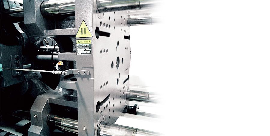
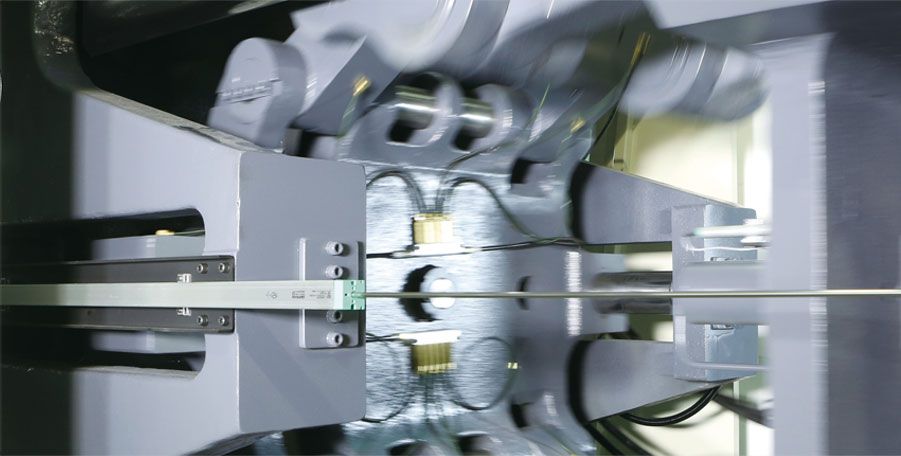
The movable platen has a box-shaped design with a T slot and a tapped mounting layout; the thickness and rigidity of the platen are both strengthened to minimize its deformation. A self-lubricated compound plate is supported at the bottom to reduce the friction of the plate with the steel tape. The layout of the platen mounting follows Euromap standards. Optional features such as the installation of a proportional valve for positional control or an ejector on the fly are also available.
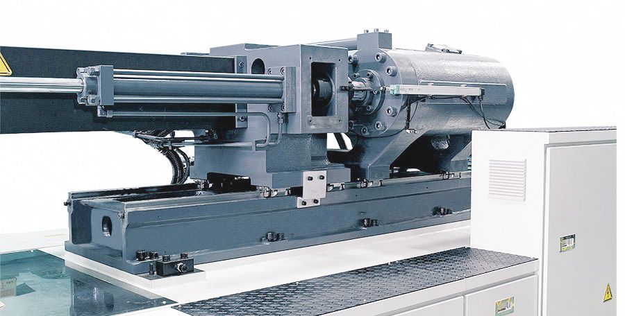
Modularized injection unit set as per injection pressure, speed, shot weight, plasticizing, etc., specifically for various molding terms. Three different options for the screw sizes are offered and may be revised on request. The movement of the double injection cylinders is supported by linear guideways to achieve a perfect positional precision and to smoothly move while performing the injection. Optional features such as a shut-off nozzle, a servo electro-driven unit, and bimetallic screw barrels are available on request.
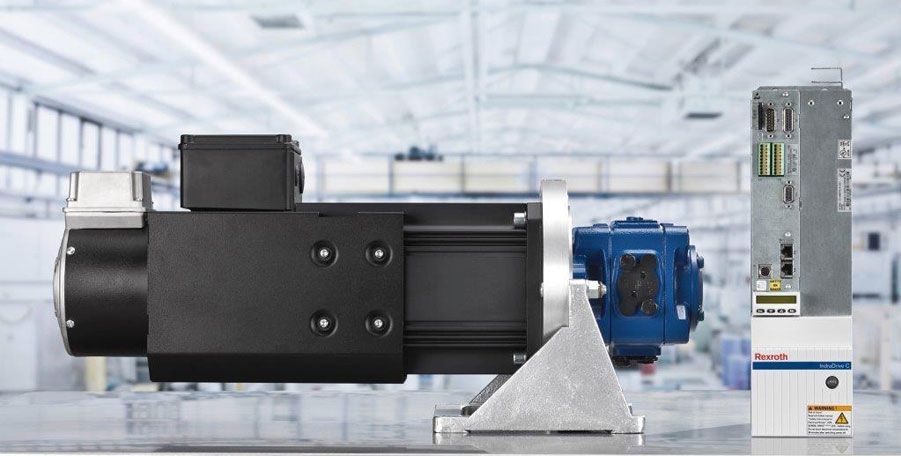
The SVP system consists of synchronous rotary speed controlled servomotor with a driver for the control section and the internal gear pump. The system software includes a set of closed loop pressure and flow controllers. The switchover from flow to pressure control and backward is done automatically by the software. The controller has been optimized to avoid pressure overshoot during the switchover from flow to pressure control. For machines requiring higher flows, a master servo unit combining single or multiple slave servo-units uses the Master-Slave System. It can provide sufficient flow for larger machines.
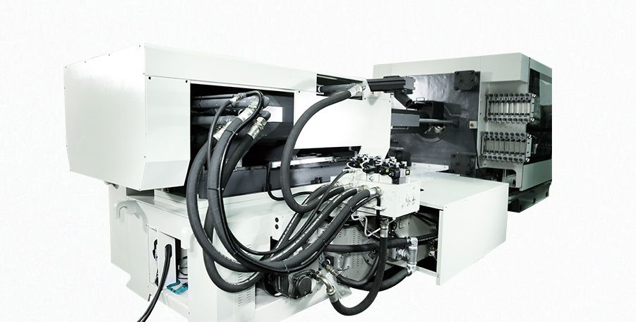
The integrated hydraulic circuit design aims to reduce efficiency loss. The standard injection and clamping manifolds have logic valves for performing with no delay and responding at the shortest time. The new servo system has no issues of heat generation from the pressure/speed proportional valve, neither of oil drain by the variable pump; the oil temperature remains stable. The consumption capacity of the oil tank is about 50% less in comparison to the conventional fixed-pump machine. In addition, on the condition of a non-stop production, the oil quality remains good as long as the temperature is stable and low. The commissioning of the high-efficiency heat exchanger also upgrades the cooling capacity of the IMM; therefore, chilling water is less consumed.
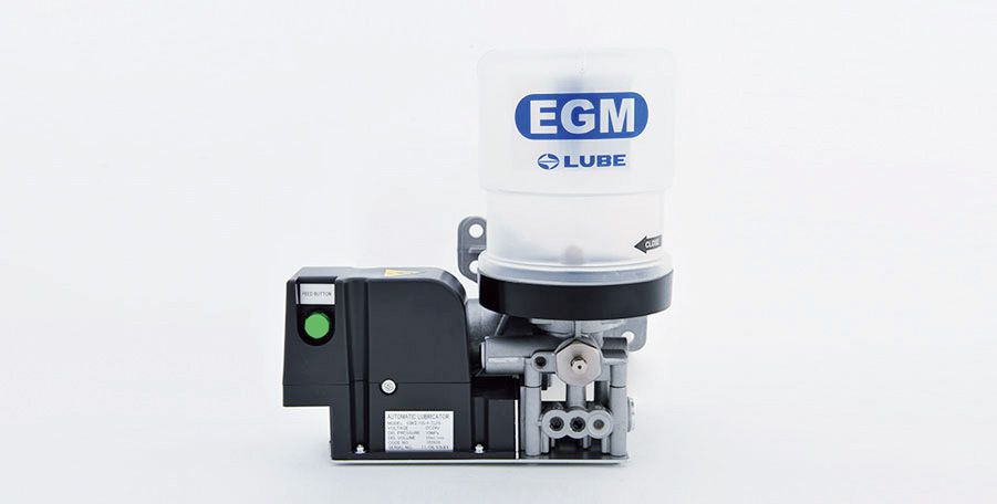
The special design of the grease medium with characteristics such as high pressure and wear-resistance can take a perfect lubrication effect on the toggle pins and bushings.
Averagely, the thousands-based frequency of the lubrication cycle reduces the grease consumption and produces less waste, and the alarm for lubrication fails prevents a short supply in case of pipe damages or a used up tube.
